Dahua HDCVI PIR Camera User’s Manual
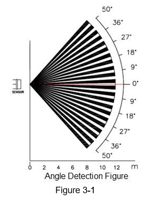
Detection Range The detection range of the detector is shown in Figure 3-1 (top view),
the horizontal angle of detection is 100°.
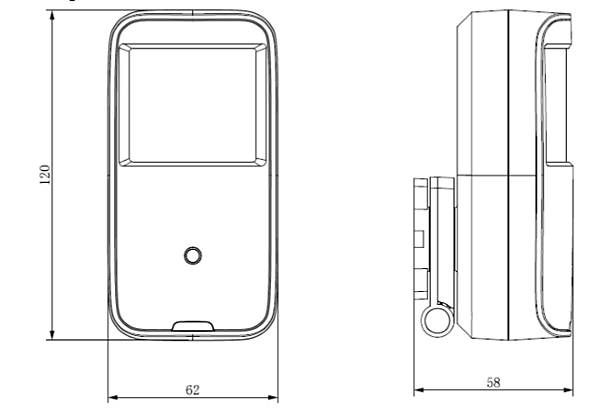
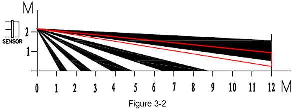
The detection range of the detector is shown in Figure 3-2 (side view),
the far distance of detection is 12m while the near distance is 1m.
The bracket supports omnidirectional rotation.
Note: The angle of detector can be adjusted according to the practical application scenario.
Device Installation
Attention:
Engineering installation and debugging have to be implemented by professional team,
please do not dismantle or repair in case of device malfunction,
you can contact the aftersale department for more information.
Try not to install the device in a location with direct sunlight.
Try not to install the device in a location with fast change of wind speed.
Try not to install the device in a location with too high temperature.
Try not to install the device in a detection range where it is blocked.
Try not to install the device in a location where there is large-scale metal product.
The installation steps of the device are shown as follows:
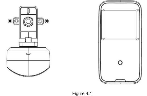
Step 1
Rotate the camera installation bracket for 90°,
which is shown in Figure 4-1.
Step 2
During installation, make sure the installation bracket bottom is parallel with the wall,
pull the cable from the outlet groove of the installation surface and use screws
to fix the camera with the wall via bracket installation hole.
Step 3
Adjust the monitoring direction of camera.
Step 4
Connect the video output port of the device to the back-end HCVR device, and connect the power port to power.
So far, the device installation and cable connection are completed,
then you can check the device monitoring image via rear-end encoding device.
Product Application
Network Access (only for –W model)
It needs to set network access of the detector before normally using wireless PIR intrusion detector.
There are two modes for network access of detector:
Connected via wireless alarm programming keyboard It needs to enable connection mode on the keyboard in this mode,
and then power on the detector,
at this moment the indicator light of the detector is normally on,
slide the tamper switch and the indicator light starts to flash. After waiting for around 10 seconds,
if the indicator light is off, then it means the detector connection is successful;
it means connection failure if the indicator light slowly flashes for three times,
then you need to repeat the above steps to get access to network.
Connection via setting MAC address In this mode,
it needs to set the detector MAC address into the MAC address list of wireless alarm controller via keyboard or client,
and then power on the detector. After waiting for around 40 seconds, if the indicator light is off,
then it means the detector connection is successful.
Note:
If the detector has been connected to other alarm controllers, then it can clear previous
connection information by quickly sliding tamper switch (5 times within 1 second).
LED Setting
You can control the status of LED indicator light via setting LED bouncing pin,
there are two statuses of LED indicator light, which are on or off.
You can set two types of value for the bouncing pin,
which are 1&2 and 2&3. It is LED OFF when selecting 1&2 and it is LED ON when selecting 2&3;
the factory default setting is LED ON.
Note: The operation causes no influence to normal work of the detector.
Pulse Count Setting
You can set pulse count bouncing pin according to the product application environment or detection distance requirement.
You can set two types of value for bouncing pin,
which are 1&2 and 2&3, it is first pulse when selecting 1&2 and it is second pulse when selecting 2&3,
the factory default setting is 1P.
The detection sensitivity of 1P is high and the detection sensitivity of 2P is low.
Installation Test
You can test the working state of the detector; the exact operation is shown as follows:
Within the detection range, it is to test with normal walk speed of 1m/s.
It means IR is triggered when the red indicator light continues to be on for 2 seconds,
the detector will get into the alarm status, output alarm signal,
at this moment the red indicator light is on. If the motion detection is enabled at this moment,
then alarm can be generated on DVR, it can also receive alarm info if it is equipped with wireless mobile portable terminal.
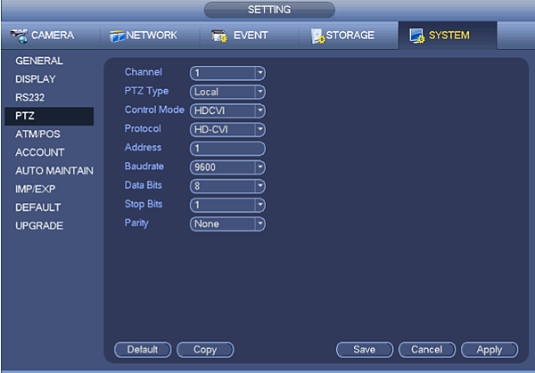
HCVR Settings
This HDCVI camera series can adjust OSD menu via coaxial control. After connected the camera to the HDCVI series HCVR,
from Main Menu->Setting->System->PTZ,
you need to select the channel number for access and set control mode as HDCVI and the protocol as HDCVI.
Click “Save” button to save current setup.
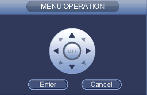
Menu Operation
Click the right mouse button and select
“PTZ Control”, then you will see the “PTZ Setup” menu

details of button functions
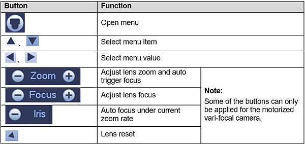
If there is “ ![]() ”, click the “Confirm” button in “Menu Operation” interface to go to the 2nd menu.
”, click the “Confirm” button in “Menu Operation” interface to go to the 2nd menu.
Click “Return” button to go back to the previous menu interface
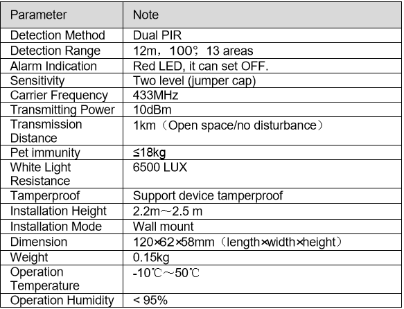
Appendix Ⅰ Technical Parameters

 留言列表
留言列表