Dahua HD Megapixel Indoor Network Camera Quick Start Guide
1 Framework
1.1 Rear Panel
Note: The figures are for reference only, which are used to know the functions of the rear panel.
Different devices may have different structures of rear panel, please refer to the actual product for more details.
See Figure 1-1.
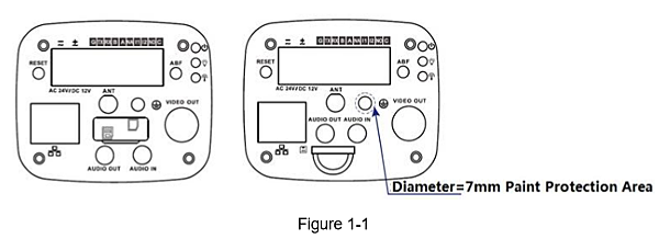
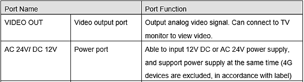
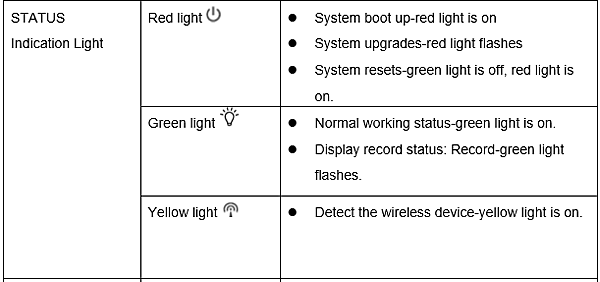
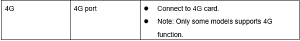
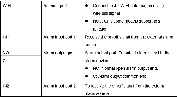
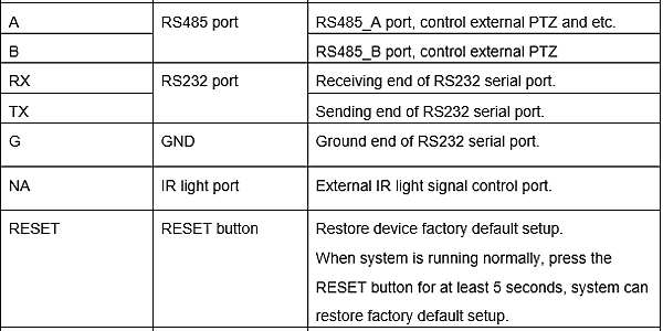
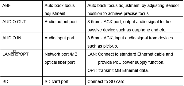
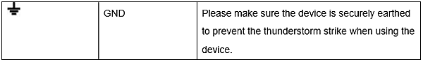
Please refer to the following sheet for detail information.
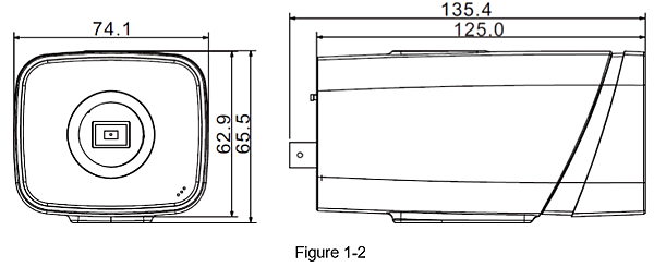
1.2 Dimension
The figures are for reference only, which are used to know the device dimension,
please refer to the actual device for more details. The unit is mm.
See Figure 1-2.
1.3 Bidirectional talk
Note: Some devices don’t support bidirectional talk, which can’t be applied to this chapter.
1.3.1 Device-end to PC Device Connection Please connect the speaker or the MIC to the audio input port in the device rear panel.
Then connect the earphone to the audio output port in the PC.
Login the Web and then click the Audio button to enable the bidirectional talk function.
You can see the button becomes orange after you enabled the audio talk function.
Click Audio button again to stop the bidirectional talk function.
Listening Operation At the device end, speak via the speaker or MIC,
and then you can get the audio from the earphone or sound box at the pc-end.
1.3.2 PC to the Device-end Device Connection Connect the speaker or the MIC to the audio input port in the PC
and then connect the earphone to the audio output port in the device rear panel.
Login the Web and then click the Audio button to enable the bidirectional talk function.
You can see the button becomes orange after you enabled the audio talk function.
Click Audio button again to stop the bidirectional talk function.
Please note the listening operation is null during the bidirectional talk process. Listening Operation
At the PC-end, speak via the speaker or MIC,
and then you can get the audio from the earphone or sound box at the device-end.
1.4 Alarm Setup
Note: Some devices don’t support alarm function, which can’t be applied to this chapter.
The alarm interface is shown as in Figure 1-3
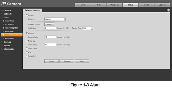
The alarm input, output connection description:
Step 1.Connect the alarm input device to the IN alarm input port on the rear panel I/O port.
Step 2.Connect the alarm output device to the NO alarm output port and C alarm output public
port on the rear panel I/O port. The alarm output port supports NO (normal open) alarm device only.
Step 3.Open the Web; go to the Figure 1-3. Here you can set the alarm input setup and alarm output setup.
Here the alarm input is the alarm input on the rear panel I/O port (as IN port).
Then you can select the corresponding type (NO/NC) according to the high/low level type when an alarm occurs.
Step 4.Set the WEB alarm output.
The alarm output 01 is the alarm output port of the device rear panel I/O port (as the NO port).
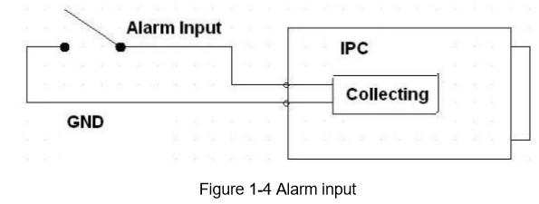
1.4.1 Alarm Input and Output Connection Please refer to the following figure for alarm input information.
See Figure 1-4.
Alarm input: When the input signal is idle or grounded,
the device can collect the different statuses of the alarm input port.
When the input signal is connected to the 3.3V or is idle, the device collects the logic “1”.
When the input signal is grounded, the device collects the logic “0”.
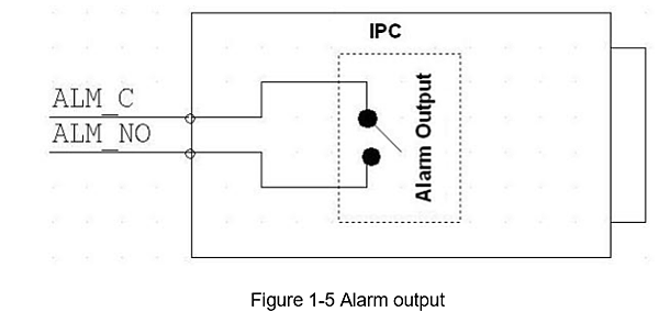
Please refer to the following figure for alarm output information.
See Figure 1-5. Port NO and Port C composes an on-off button to provide the alarm output.
If the type is NO, this button is normal open.
The button becomes on when there is an alarm output.
If the type is NC, this button is normal off.
The button becomes off when there is an alarm output.
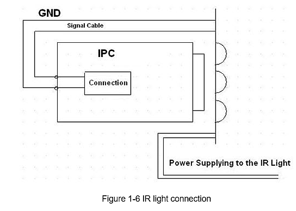
1.4.2 IR Light Connection
Note:
Device shall have external port for IR function.
Log in Web, select Setup -> Camera -> Day&Night, and select sensor input.
If it is not available, then you do need to set it.
Please refer to the following figure for external IR light information. See Figure 1-6.
IR synchronization input signal.
When the external IR light is on, the signal cable from the board outputs the 3.3V/1mA.
It outputs the 0V when the IR light is off.
2 Installation
2.1 Lens Installation
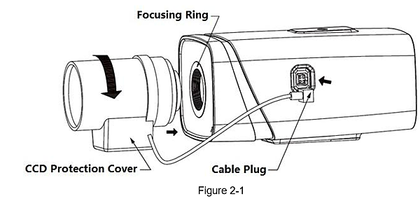
2.1.1 Auto Aperture Lens Installation
Step 1 Remove the CCD protection cover on the device, aim the lens at the lens installation position,
and turn the lens clockwise until it is installed firmly.
Step 2 Insert the lens cable plug into the connector of auto aperture lens on the camera side panel.
Step 3 Make the image clear via adjusting focal length.
2.1.2 Manual Aperture Lens Installation Please follow the steps listed below for auto aperture lens installation.
Step 1 Remove the CCD protection cap of the device,
Step 2 Install the C/CS adapter ring on the camera;
turn clockwise to the end to cling to the focusing ring on the camera closely.
(Only C lens needs to install adapter ring)
Step 3 Aim the C port lens at the lens installation position of the C/CS adapter ring
(aim the CS port lens at the lens installation position of the camera focusing ring);
turn the lens clockwise until it is firmly installed.
Step 4 Use slotted screwdriver to unfasten the screw near the focusing ring
and then turn counter clockwise to move the focusing ring out for several millimeters.
Now you can focus manually and check the video is clear or not.
If you can’t see the clear video, you can adjust back focus.
Step 5 After you completed the focus setup,
use the slotted screwdriver to fix the screw firmly.
Fasten the focusing ring. Now the installation completed.
2.2 SD Card/SD Card Installation
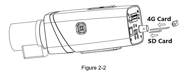
Step 1 Take down the SD card/4G card protection cover from the device.
Step 2 Install the SD card/4G card into the device according to the installation direction shown in Figure 2-2.
Step 3 Cover the SD card/4G card protection cover.
Step 4 Fix the SD card/4G card protection cover on the device.
2.3 WIFI Antenna Installation
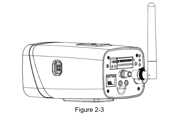
Step 1 Face screw on WIFI antenna toward bolt of port on rear panel.
Rotate according to the figure 2-3 until the antenna is fixed in place.
Step 2 After WIFI antenna is fixed on WIFI port on rear panel,
you can adjust direction of WIFI antenna according to actual need.
2.4 I/O Port Application
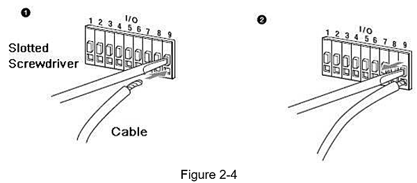
Install Cable:
Step 1 Use the small slotted screwdriver to press the corresponding button of cable groove.
Step 2 Insert the cable into the groove.
Step 3 Release the screwdriver which presses the groove button and complete cable installation.
3 Network Configuration
The IP address of all the cameras is the same when leaving factory
(default IP192.168.1.108),
in order to make the camera get access to the network smoothly,
please plan the useable IP segment reasonably according to the actual network environment.
3.1 Modify IP Address
IP address can be acquired and modified through quick configuration tool for the cameras which are accessed via wired network,
it needs to connect wired network to configure wireless parameters before using wireless network cameras. In this chapter,
it will introduce the approach of modifying IP address via “Quick Configuration Tool”;
also you can modify the IP address in the network parameters of the WEB interface,
please refer to the document in the disk << WEB Operation Manual>> for more details.
Note:
Currently the quick configuration tool only supports the cameras which apply to the same network segment with computer IP address.
Step 1 Double click the “ConfigTools.exe” and open the quick configuration tool.
Step 2 Double click the device to be configured, the system will pop out the “Login” dialog box. Enter the IP address
, user name, password and port number of the camera, and click “Confirm”.
Note:
The default user name and password are admin and admin respectively,
the default of port is 37777.
See Figure 3-1 for more details.
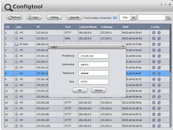
Figure 3-1
Step 3 Modify the camera IP address on the “Net” interface,
click “Save” to finish modification.
See Figure 3-2 for more details.
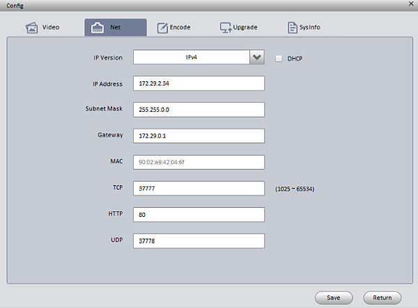
Figure 3-2
3.2 Login WEB Interface
Note: Different devices may have different WEB interfaces, the figures below are just for reference,
please refer to the document <<WEB Operation Manual>>
in the disk and the actual interface for more details
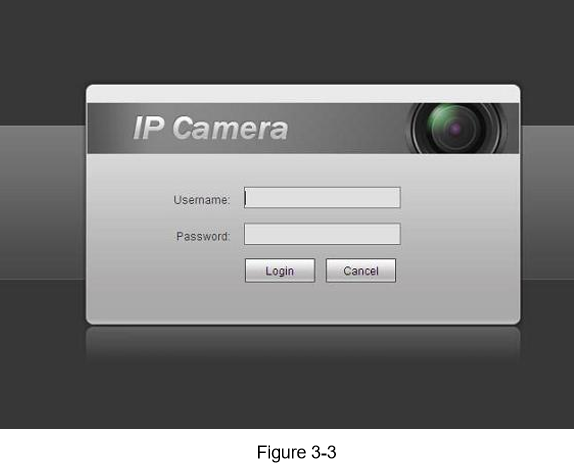
Step 1 Open IE and input the modified camera IP address in the address bar.
Step 2 The login interface is shown below, please input your user name and password
(Default user name is admin and password is admin respectively), click “login”.
See Figure 3-3 for more details.
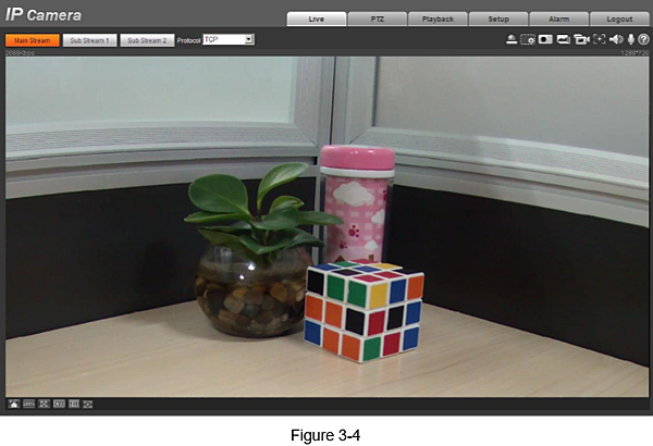
Step 3 Install controls according to the system prompt;
see Figure 3-4 for the WEB main interface.
Please modify the administrator password as soon as possible after you successfully logged in.

 留言列表
留言列表